¶ 1. Prerequisites
- A CH341A-based flasher
- Either a soldering iron or an SPI clip
- The new firmware file (download it from here)
- Another device with Linux installed (Windows should work too, but is not covered here)
A very handy pack including the flasher, clip, and other useful accessories can be ordered here:
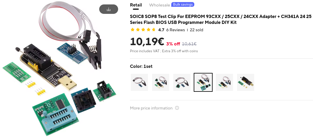
If the link has expired, feel free to give us a heads-up on Discord or Telegram.
¶ 2. Connect to SPI
Before connecting anything to power, double-check that all connectors are correctly oriented!
The simplest way to connect to the SPI chip is by using the clip. It can be a bit tricky to get a firm connection, but it doesn't require any soldering skills or tools. Additionally, using the clip is very unlikely to cause any damage to the board.
On the other hand, if you have soldering experience, it's not a difficult task to desolder and resolder the eight pins of the SPI chip.
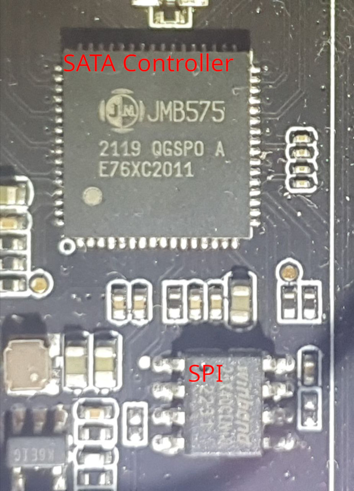
- The SPI chip is located near the SATA ports, right next to the mSATA slot. Look for the square chip labeled "JMB575" — that's the SATA controller. Next to it, you'll find a smaller 8-pin chip labeled "W25X40CL", which is the SPI chip. The label on the SPI chip can be hard to read, but once you've located the SATA controller, it should be easy to identify the SPI chip.
SATA Controller and SPI Chip
¶ 2.1 Connect the Clip
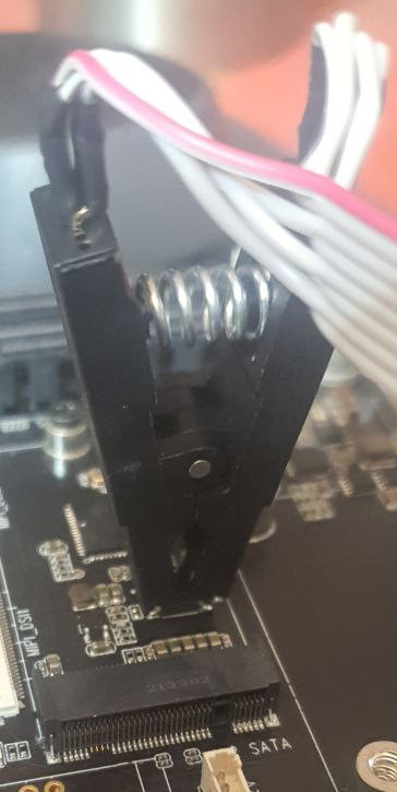
Pin 1 on the clip is color-coded on the cable — the red wire indicates it. The red wire should face the edge of the board where the SATA ports are located.
- Make sure the clip is fully inserted. If it's connected correctly, you should be able to lift the board using the clip.
Orientation of the clip connected to the SPI
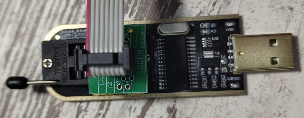
- Connect the other end of the cable to the flasher. The correct orientation is as follows: if the USB connector of the flasher is pointing towards you, the cable should go into the lower four holes, with the red wire in the top left corner.
Orientation of the clip connected to the flasher
¶ 2.2 Or desolder the SPI Chip
Grab some soldering wick and flux, heat up your iron, and desolder the chip. You should know what you're doing!
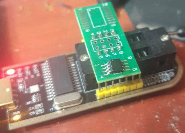
You can then either solder the chip directly onto the flasher (there’s a pad on the back of the flasher for this), or use one of the adapter boards included in the pack mentioned above.
There should be an unpopulated board and a ZIF Socket as part of the pack. Choose wisely.
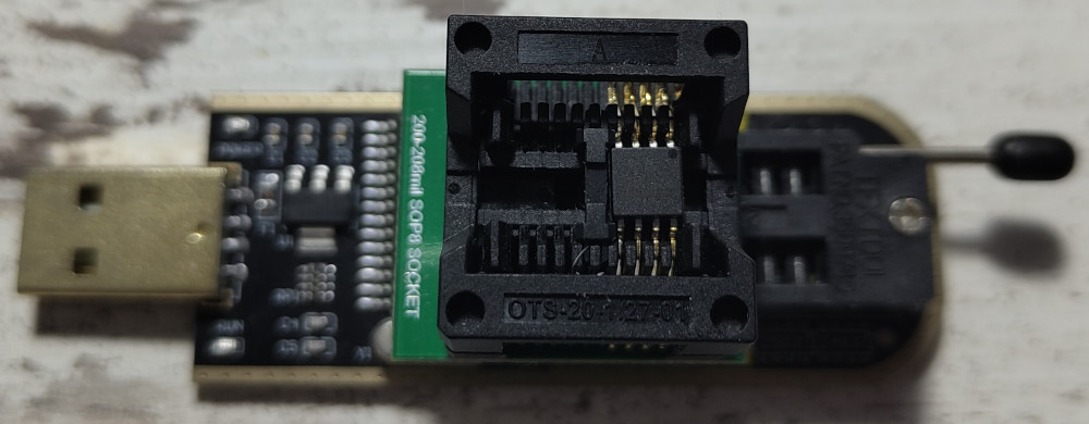
Pin 1 is marked on the chip with a small dot and is labeled with a "1" on the flasher or adapter board.
SPI Chip connected to Flasher through a ZIF Socket
SPI Chip soldered to the adapter board
¶ 2.3 Check connection
- First you need to install flashrom.
sudo pacman -S flashrom
Ensure that your flasher is set to 3.3 volts!
Check all cables and make sure your ITX-3588J board is disconnected from power if you're using the clip.
Then, connect the flasher to your Linux device and run the following command.
- If it reports the SPI chip name mentioned above, you're good to go.
sudo flashrom -p ch341a_spi --flash-name
flashrom 1.4.0-devel (git:v1.2-1355-g9ccbf1cf) on Linux 6.15.7-1-BredOS (x86_64)
flashrom is free software, get the source code at https://flashrom.org

Using clock_gettime for delay loops (clk_id: 1, resolution: 1ns).
Found Winbond flash chip "W25X40" (512 kB, SPI) on ch341a_spi.
If it does not, check the connection of your clip or inspect your soldering work, and verify the orientation of all connectors.
¶ 3. Flash Firmware
¶ 3.1 Backup Old Firmware
Before flashing a new ROM, it's a good idea to back up the existing one.
If anything goes wrong, you'll be able to restore it using this backup.
- Dump the flash with the following command:
sudo flashrom -p ch341a_spi -r firmware_dump.bin
- Then, dump it again and compare the two files to ensure the data was transferred correctly.
sudo flashrom -p ch341a_spi -r firmware_dump-1.bin
diff firmware_dump.bin firmware_dump-1.bin
If "diff" produces no output, you're good to go.
If it does, check the connection of your clip or inspect your soldering work, and verify the orientation of all connectors.
¶ 3.2 Flash new Firmware
- As simple as the title suggests:
sudo flashrom -p ch341a_spi -w sata_adapter_EN25F40.bin
flashrom 1.4.0-devel (git:v1.2-1355-g9ccbf1cf) on Linux 6.15.7-1-BredOS (x86_64)
flashrom is free software, get the source code at https://flashrom.org

Using clock_gettime for delay loops (clk_id: 1, resolution: 1ns).
Found Winbond flash chip "W25X40" (512 kB, SPI) on ch341a_spi.
===
This flash part has status UNTESTED for operations: WP
The test status of this chip may have been updated in the latest development
version of flashrom. If you are running the latest development version,
please email a report to flashrom@flashrom.org if any of the above operations
work correctly for you with this flash chip. Please include the flashrom log
file for all operations you tested (see the man page for details), and mention
which mainboard or programmer you tested in the subject line.
Thanks for your help!
Reading old flash chip contents... done.
Erase/write done from 0 to 7ffff
Verifying flash... VERIFIED.
If you see the text "VERIFIED," the firmware has been flashed correctly. If you used the clip, simply disconnect it and you're good to go. If you desoldered the chip, you know what to do.
All SATA Ports should work fine now!